
Table of Contents
Ⅰ. Introduction
Micro-precision fiber laser cutting has emerged as the definitive manufacturing solution for industries where dimensional tolerances, edge quality, and material integrity are non-negotiable. Unlike conventional fiber laser systems that operate with kerf widths of 100–300 µm and tolerance bands of ±50 µm to ±100 µm, micro-precision systems achieve positional accuracy in the single-digit micron range and kerf widths as narrow as 8 µm. This capability is reshaping how precision engineering firms approach thin foil cutting, titanium cutting, and the fabrication of complex micro-components for medical, aerospace, and electronics sectors. As component miniaturization accelerates and material costs rise, manufacturers are increasingly questioning whether their legacy cutting methods can deliver the yield, speed, and repeatability that modern high-tech production demands.
Ⅱ. Mission-Critical Applications in High-Tech & Precision Sectors
1. Medical Device Manufacturing
The medical device industry represents one of the largest adopters of micro-precision laser technology. Fiber lasers are used to fabricate life-saving devices with extreme precision, including cardiovascular stents, surgical instruments, and implantable components. Micro-precision fiber laser cutting enables the production of stent struts on nitinol tubing, hypotube slotting for catheters, and precision sensor diaphragms on stainless steel. For titanium Grade 2 and Grade 5 foils in the 0.05–0.3 mm range, fiber laser systems produce clean cuts when paired with argon assist gas, preserving the medical-grade edge chemistry required for implantable devices. The heat-affected zone (HAZ) on stainless steel 304 and 316L foils measures 8–15 µm on standard fiber systems and drops below 5 µm when picosecond UV sources are employed.
2. Aerospace & Defense Components
In aerospace manufacturing, laser cutting has become indispensable due to its unmatched accuracy, minimal waste, and high-speed processing. Fiber laser cutting machines are the industry’s go-to technology, delivering fast, accurate cuts on reflective and heat-sensitive metals like aluminum, titanium, and nickel alloys. Titanium weighs approximately half as much as steel while delivering comparable structural performance, making it ideal for lightweight brackets and shims. For defense applications, precision-cut titanium shims and sensor housings must maintain structural integrity across extreme temperature ranges.
3. Electronics & Semiconductor Fabrication
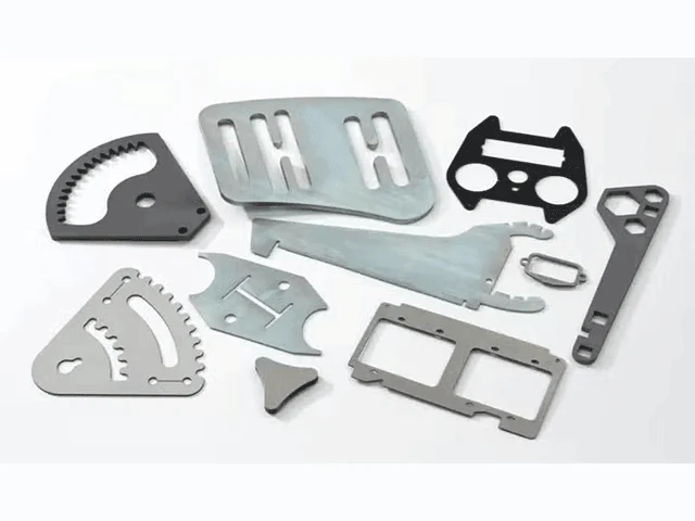
The electronics industry relies heavily on the precision cutting capabilities of laser technology for the miniaturization of electronic devices. RF shield apertures on copper alloy foils and miniature connector housings demand feature sizes below 500 µm—a domain where micro-precision fiber laser cutting has displaced traditional stamping and EDM processes for materials under 0.3 mm thickness. Thin metal foils are extensively used in electronics for flexible circuits, EMI/RFI shielding, and connectors due to their excellent electrical conductivity and precise tolerances.
| Application Sector | Typical Material | Thickness Range | Critical Feature Size | HAZ Requirement |
|---|---|---|---|---|
| Medical Stents | Nitinol / 316L SS | 0.05–0.30 mm | 25–100 µm | < 5 µm |
| Aerospace Shims | Titanium Grade 5 | 0.10–0.50 mm | 50–200 µm | < 15 µm |
| Electronics Shields | Copper Alloy | 0.05–0.20 mm | 50–500 µm | < 10 µm |
| Sensor Diaphragms | 316L SS | 0.05–0.15 mm | 25–100 µm | < 8 µm |
| Surgical Instruments | 304 SS / Titanium | 0.10–0.40 mm | 100–300 µm | < 10 µm |
Ⅲ. The Physics and Process Science of Micro-Precision
1. Beam Quality and the M² Factor
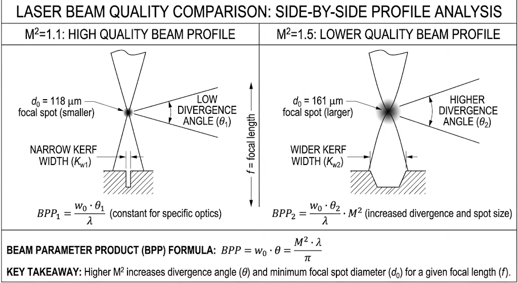
The foundation of micro-precision fiber laser cutting lies in beam quality, quantified by the M² factor. The M² factor is defined as the beam parameter product divided by the corresponding product for a diffraction-limited Gaussian beam with the same wavelength, with M² = 1 representing a perfect Gaussian beam. Leading fiber laser systems achieve M² values below 1.1, enabling diffraction-limited focusing to spot diameters of 10–20 µm. Under fixed optical conditions, a lower and more symmetric M² factor helps achieve a smaller focused spot, higher equivalent average power density, and more stable performance in precision processing. The focused spot diameter is approximately proportional to M², meaning a beam with M² = 1.5 produces a spot roughly 36% larger than one with M² = 1.1 under identical optical conditions.
2. Thermal Dynamics and Heat-Affected Zone Control
The heat-affected zone does not depend only on power. It is closely related to the balance between energy deposition rate and cutting speed. Lower M² beams concentrate energy more effectively, enabling higher cutting speeds that leave less time for heat to diffuse sideways, resulting in smaller HAZ. Cutting speed scales non-linearly with material thickness: on 0.05 mm 304 stainless, mid-power fiber runs at 250–300 mm/s; at 0.1 mm, this drops to 150 mm/s; and at 0.3 mm, it slows to 40–60 mm/s. This inverse-quadratic relationship arises because energy delivery must match a melt volume that scales with thickness squared at constant kerf.
3. Assist Gas Dynamics and Nozzle Engineering
Assist gas selection directly impacts edge quality, HAZ extent, and oxidation levels. Most laser micro cutting on stainless and titanium uses nitrogen to suppress oxidation, with a productive pressure window between 0.8 MPa and 1.1 MPa for 0.1 mm 304 stainless foil. Nozzle stand-off for foils under 0.3 mm ranges from 0.3 mm to 0.8 mm; closer than 0.3 mm risks nozzle contamination, while beyond 0.8 mm the gas column loses coherence. Beam waist positioning relative to the workpiece surface determines kerf taper: with the waist at the top surface, taper angles run 3°–5° on 0.3 mm material; repositioning the waist to one-third depth reduces taper to under 1°.
| Physics Parameter | Standard Fiber Laser | Micro-Precision Fiber Laser | Impact on Cut Quality |
|---|---|---|---|
| M² Factor | 1.3–2.0 | < 1.1 | Smaller spot, higher power density |
| Focused Spot Diameter | 50–100 µm | 10–20 µm | Narrower kerf, finer features |
| HAZ on 304 SS | 20–40 µm | 8–15 µm | Reduced thermal distortion |
| Positional Accuracy | ±50–100 µm | ±5–20 µm | Tighter tolerances |
| Kerf Width | 100–300 µm | 8–35 µm | Higher material yield |
Ⅳ. The Economic Equation: Cost Dynamics & ROI in High-Value Fabrication
1. Material Yield and Kerf Optimization
For manufacturers processing expensive materials like titanium, beryllium copper, or medical-grade stainless steel, kerf width must be treated as a yield specification—not merely a geometry specification. Micro-precision fiber laser cutting maintains kerf widths 65% narrower than plasma cutting, with thermal distortion limited to 0.08 mm/m in stainless steel. Kerf width scales non-linearly with thickness: a 0.1 mm cut might have a 15 µm kerf, while the same parameters on 0.25 mm foil produce a 28 µm kerf rather than a proportional 38 µm. Understanding this scaling behavior is essential for nesting optimization and material yield calculations in thin foil cutting operations.
2. Prototyping Velocity and Tooling Elimination
Sub-0.3 mm feature work requires setup validation cuts and parameter calibration per material batch. The first 20–50 pieces of any new geometry run are qualification pieces, not production output. However, once parameters are locked, micro-precision fiber laser cutting enables rapid design iteration without hard tooling. Digitally controlled, repeatable processes allow faster product changeovers and global production line consistency. For prototype runs under 100 parts, the source-cost premium is usually absorbed in setup time; for production runs above 10,000 parts, designers should evaluate whether thermal-sensitive material choices are truly required.
3. Payback Timeline and Operational Economics
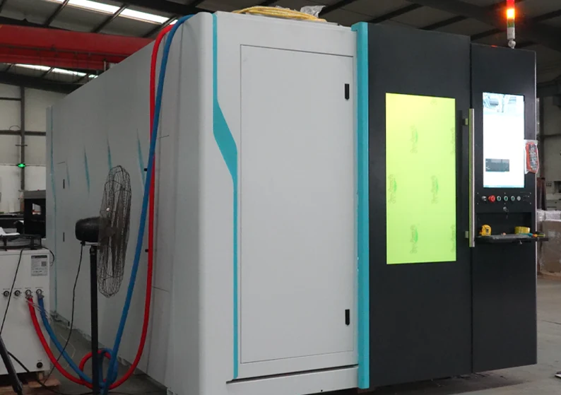
The ROI timeline for precision laser systems varies by production volume and application. A high-production shop can achieve payback within six months to a year, while smaller operations may see returns in approximately two years. In a representative scenario comparing outsourced bracket production at $5.00 per part against in-house micro-precision fiber laser cutting, annual savings of $40,008 against a $45,000 machine investment yield a break-even point of just 13 months. The hourly operating cost for a 3 kW fiber laser system runs approximately $30.25, while market laser cutting rates charge between $150 and $300 per hour of beam-on time, generating roughly $120 of net profit per operational hour.
| Cost Component | Outsourced Production | In-House Micro-Precision Laser | Annual Delta |
|---|---|---|---|
| Material Cost (1,000 parts/mo) | Included in vendor price | $1,500/month | Baseline |
| Cutting / Machine Cost | N/A | $166/month | +$166 |
| Total Monthly Cost | $5,000 | $1,666 | –$3,334 |
| Annual Cost | $60,000 | $19,992 | –$40,008 |
| Lead Time | 10 days | 1 day | –9 days |
| Break-Even Period | N/A | 13 months | — |
Ⅴ. Strategic Integration: Deploying Advanced Laser Systems into High-Tech Workflows
1. Source Selection by Material and Feature Scale
The selection of micro-precision fiber laser cutting equipment follows a four-variable decision matrix. For materials below 0.1 mm, picosecond UV is preferred for thermally sensitive substrates, while standard fiber handles routine stainless steel processing. From 0.1 mm to 0.3 mm, mid-power fiber (200–500 W) addresses most applications. Above 0.3 mm, higher-power fiber becomes appropriate. Features under 25 µm require picosecond or femtosecond sources with focused spot diameters under 15 µm; features in the 25–100 µm range are within fiber capability with proper optics. Ultrafast laser hourly rates run 2–4× fiber rates at most contract shops, so volume and cost must be balanced against thermal sensitivity requirements.
2. Motion Control and Real-Time Feedback Architecture
High-precision linear stages with sub-micron repeatability guide the laser beam across the workpiece. Real-time feedback systems make thousands of power and focal adjustments per second based on sensor readings from the cutting area, correcting abnormalities to maintain optimal cutting conditions. This closed-loop adaptive control is validated through production runs exceeding 10,000 parts, maintaining consistent tolerance across entire batches. Engineers should note that datasheet specifications listing positional accuracy of ±0.01 mm without specifying material, thickness, ambient temperature, or duty cycle represent laboratory measurements; production environments rarely replicate controlled conditions.
3. Quality System Alignment and Process Validation
For medical and aerospace work, ISO 13485 Section 7.5.6 expects documented validation for any process whose output cannot be fully verified by subsequent inspection. Most laser micro cutting falls in this category. A mature shop has documented containment, root-cause, and corrective-action procedures with stated response times. When evaluating suppliers, verify the certification scope—what processes, facilities, and product categories are actually covered—rather than accepting ISO 9001 alone as evidence of fitness for medical or aerospace work.
| Selection Variable | < 0.1 mm Thickness | 0.1–0.3 mm Thickness | > 0.3 mm Thickness |
|---|---|---|---|
| Preferred Source | Picosecond UV | Mid-Power Fiber (200–500 W) | High-Power Fiber |
| Min. Feature Size | < 25 µm | 25–100 µm | > 100 µm |
| HAZ Target | < 5 µm | 8–15 µm | 15–30 µm |
| Relative Hourly Rate | 2–4× fiber | Baseline | Baseline |
| Best For | Nitinol, polyimide | Stainless, titanium | Thick structural metals |
Ⅵ. FAQ
Q1: What thickness range can micro-precision fiber laser cutting handle?
Micro-precision fiber laser cutting effectively processes materials from approximately 5 µm to 1.5 mm, with the most productive commercial range spanning 0.05 mm to 0.5 mm. For thin foil cutting below 0.1 mm, specialized picosecond UV sources may be recommended to minimize thermal damage.
Q2: Is titanium cutting safe with fiber laser systems?
Yes. Titanium Grade 2 and Grade 5 in the 0.05–0.3 mm range cut cleanly on fiber laser systems when argon assist gas is employed. Argon prevents edge oxidation and preserves the material’s corrosion-resistant properties, making it suitable for medical and aerospace applications.
Q3: How does micro-precision laser cutting compare to EDM or stamping?
For production environments under 0.3 mm thickness, micro-precision fiber laser cutting has largely displaced stamping, EDM, and mechanical micromachining. It offers faster setup, no hard tooling costs, and the ability to produce complex geometries without material deformation.
Q4: What ROI should I expect from investing in a precision laser system?
High-production facilities typically achieve payback within 6–18 months. Key factors include eliminating outsourcing costs, reducing scrap rates, and maximizing material yield through narrower kerf widths. Even a 1% yield improvement can outweigh consumable costs in high-value material processing.
Q5: How do I verify that a machine’s accuracy claims are realistic?
Request specifications that include material type, thickness, ambient temperature, and duty cycle. Lab-measured accuracy rarely translates directly to production floor performance. Always demand validation cuts on your specific material batch before purchase.
Q6: Can your company provide custom micro-precision cutting solutions?
WSLLASER specializes in designing and manufacturing laser cutting machines tailored to precision engineering requirements. While we do not produce accessories, our deep understanding of optical systems, motion control, and assist gas strategies ensures that every machine we deliver is optimized for demanding thin foil cutting and titanium cutting applications.
Ⅶ. Conclusion
Micro-precision fiber laser cutting has transitioned from a specialized niche to a core manufacturing capability for precision engineering and high-tech industries. By delivering sub-micron accuracy, minimizing heat-affected zones, and maximizing material yield through narrow kerf widths, this technology offers a compelling alternative to traditional machining methods. The business case is equally persuasive: facilities running high-volume production can recover their investment within 13–18 months through reduced scrap, eliminated outsourcing costs, and superior nesting efficiency. For manufacturers evaluating their next capital equipment purchase, the critical decision is not whether laser precision is achievable, but whether selecting the right configuration—balancing power, wavelength, motion control, and gas strategy—can transform their production economics. As component miniaturization continues across medical, aerospace, and electronics sectors, the question is no longer if micro-precision fiber laser cutting belongs in your facility, but how quickly you can integrate it.