
The decision between a fiber laser and a CO2 laser is no longer a debate about cut quality. It is a capital allocation decision about electrical load, consumable burn rate, and whether the shop can afford to keep an aging gas-discharge resonator running through a second shift.
This guide compares fiber laser vs CO2 laser systems on the metrics that matter to a plant manager: wall-plug efficiency, cutting speed at each thickness band, five-year maintenance exposure, and the realistic payback timeline for replacing a CO2 bed with a fiber cell. For a broader view of how the laser cell fits into workshop layout and material flow, review our CNC laser cutting machine guide, and for the full hourly operating ledger behind these figures, see the laser cutter cost per hour breakdown.
Ⅰ. Optical Architecture & Power Efficiency: Fiber Laser vs. CO2 Laser Systems
1. Solid-state diode pumping vs. RF gas discharge excitation
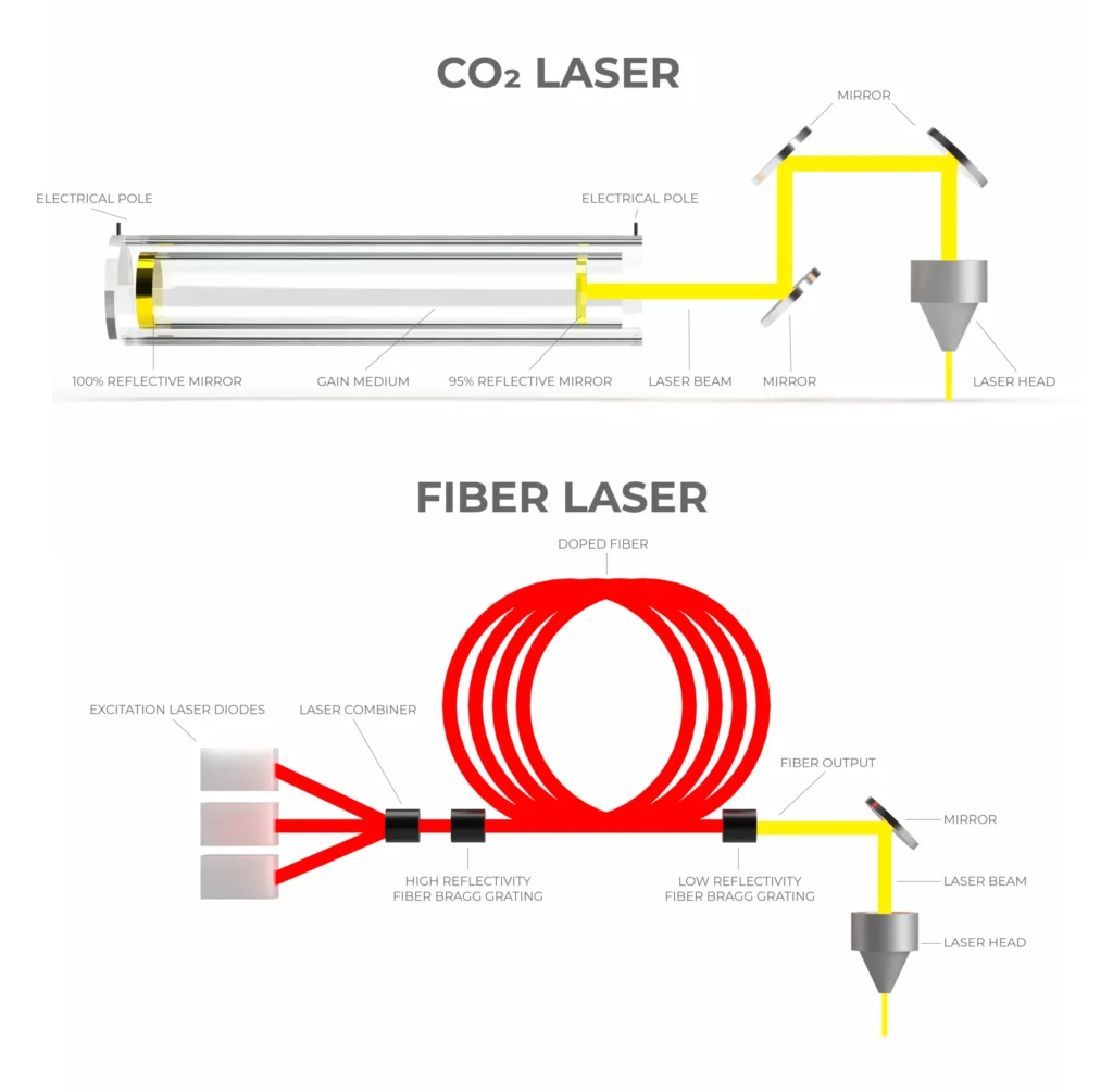
A fiber laser generates light inside a doped silica fiber, pumped by solid-state diodes. A CO2 laser generates light in a gas mixture of CO₂, N₂, and helium, excited by an RF discharge and delivered through an external mirror path. The architectural difference determines everything downstream: maintenance surface, beam delivery reliability, and electrical appetite.
The fiber architecture has no gas refill, no turbine blower, no mirror alignment, and no resonator optics exposed to contamination. The CO2 architecture has all four.
2. Wall-plug efficiency and electrical grid load reduction
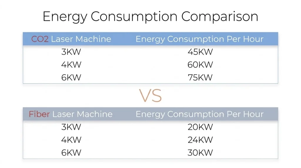
This is where fiber laser vs CO2 laser diverges most sharply for facility planning. A fiber source converts 35–40% of grid power into laser light. A CO2 source converts 8–10%. For the same delivered cutting power, the CO2 system draws roughly four times the electrical current and rejects the remainder as heat into the chiller loop.
On a 6kW comparison, the fiber cell draws approximately 18–22 kW at the wall. The CO2 equivalent draws 60–75 kW. That gap determines transformer size, chiller capacity, and monthly utility billing before a single part is cut.
Table 1: Technical & Optical Specifications: Fiber vs. CO2 Laser
| المعلمة | ليزر الألياف | CO2 Laser |
|---|---|---|
| الطول الموجي | 1.064 μm | 10.6 μm |
| Wall-plug efficiency | 35–40% | 8–10% |
| Beam delivery | Flexible fiber cable | External mirror path |
| Resonator gas consumption | لا شيء | CO₂/N₂/He mixture, continuous |
| Mirror alignment required | لا | Yes, periodic |
| Typical maintenance interval | 2,000–4,000 hours (protective window) | 500–1,000 hours (mirror clean, gas check) |
| Transformer load for 6kW class | ~20 kW | ~70 kW |
Ⅱ. Cutting Speed & Thickness Crossover Point (1mm to 20mm Metal Sheets)
1. Thin-gauge velocity advantage and absorption physics
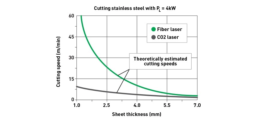
At 1.064 μm, fiber laser energy is absorbed far more efficiently by steel, stainless, and aluminum than at 10.6 μm. The practical result on 1–4 mm sheet is a 3–4× feed rate advantage over CO2 at equivalent power. On 2 mm stainless, a 6kW fiber cell cuts at 25–30 m/min; a comparable CO2 cell runs 8–10 m/min.
For a job shop running thin-gauge production, this speed gap converts directly into throughput: same floor space, same labor, three to four times the finished parts per shift.
2. Thick plate performance: The 16mm–20mm transition boundary
إن fiber laser vs CO2 laser comparison shifts as thickness increases. CO2 maintains a narrow, clean kerf on 16–20 mm carbon steel with oxygen assist, and some fabricators still prefer it for very thick plate where edge finish is critical. Fiber at 12–20 kW closes most of that gap, but the economic case at 20 mm depends on volume and secondary-operation elimination rather than raw speed.
For most shops cutting 1–12 mm as the core workload, fiber wins on every metric. For 16–20 mm as the dominant thickness, the decision requires a volume-based TCO model rather than a speed table alone.
Table 2: Cutting Speed by Thickness (1mm–20mm Stainless & Carbon Steel)
| السماكة | المواد | Fiber 6kW (m/min) | CO2 4kW (m/min) | Speed Ratio |
|---|---|---|---|---|
| 1 mm | Stainless | 35–40 | 10–12 | 3.5× |
| 2 mm | Stainless | 25–30 | 8–10 | 3.0× |
| 4 mm | Stainless | 12–15 | 4–5 | 3.0× |
| 6 mm | الفولاذ الكربوني | 5.5–6.5 | 2.2–2.8 | 2.3× |
| 10 ملم | الفولاذ الكربوني | 2.5–3.0 | 1.5–1.8 | 1.7× |
| 16 mm | الفولاذ الكربوني | 1.2–1.5 | 1.0–1.2 | 1.2× |
| 20 ملم | الفولاذ الكربوني | 0.8–1.0 | 0.9–1.0 | 1.0× |
Reference speeds for oxygen-assisted carbon steel and nitrogen-assisted stainless; confirm against specific machine and gas supply.
Ⅲ. Maintenance Ledger: Beam Delivery & Zero-Mirror Maintenance
1. Eliminating flying optics and external alignment downtime
A CO2 system delivers beam through a chain of water-cooled bending mirrors mounted on the gantry. Each mirror surface degrades with dust and spatter, and each requires periodic alignment. Every alignment event is production downtime, and every misalignment is a scrap risk.
A fiber system delivers beam through a sealed flexible cable. There is no external mirror to clean, align, or replace. The only optical maintenance point is the protective window at the cutting head—a consumable that costs a fraction of a mirror set and can be swapped in minutes.
2. Laser gases, turbine blowers, and optical wear components
The CO2 resonator consumes a continuous gas mixture and depends on a high-speed turbine blower for gas circulation. Both are recurring costs: gas refills, blower service, and eventual turbine overhaul. The fiber resonator has none of these systems.
This is where the fiber laser vs CO2 laser maintenance gap becomes most visible on the annual budget: the CO2 line carries gas, blower, mirror, and tube-replacement exposure; the fiber line carries protective windows, nozzles, and chiller service.
Table 3: 5-Year Maintenance Ledger: Consumables & Optical Upkeep
| فئة التكلفة | Fiber Laser (5-Year) | CO2 Laser (5-Year) |
|---|---|---|
| Resonator gas refill | $0 | $8,000–$15,000 |
| Turbine blower service/overhaul | $0 | $6,000–$12,000 |
| External mirror replacement | $0 | $4,000–$8,000 |
| Protective windows & nozzles | $3,000–$6,000 | $3,000–$6,000 |
| Chiller service | $1,500–$3,000 | $4,000–$7,000 |
| Estimated 5-year total | $4,500–$9,000 | $25,000–$48,000 |
Estimates based on dual-shift operation; actual figures depend on duty cycle, gas purity, and shop environment.
Ⅳ. Financial Ledger: Annual Operating Cost & ROI Payback Comparison
1. Dual-shift operating expense model
At 4,000 hours per year, the electrical gap between a 6kW fiber cell and a comparable CO2 cell runs approximately 150,000–200,000 kWh annually. At $0.12/kWh, that is $18,000–$24,000 in electricity alone—before gas, consumables, or maintenance.
Add the assist gas savings from fiber’s higher efficiency and the CO2 system’s continuous resonator gas consumption, and the annual operating gap reaches $25,000–$35,000 for a single machine.
2. Capital payback timeline for machine replacement and plant retrofit
For a shop replacing an aging CO2 bed, the payback calculation is straightforward: annual operating savings divided into the net capital cost of the fiber replacement. At $25,000–$35,000 annual savings and a net capex of $80,000–$120,000 after resale of the CO2 unit, payback lands in 8–14 months on dual-shift operation.
Under IRS Section 179, the full equipment cost can be expensed in the year placed in service, which accelerates cash recovery further. Single-shift shops see longer payback—16–24 months—because the operating hours base is halved.
Table 4: Capital Payback & Break-Even Timeline by Operating Shifts
| Operating Mode | Annual Operating Savings | Net Capex After CO2 Resale | فترة الاسترداد |
|---|---|---|---|
| Single shift (2,000 h/yr) | $12,000–$17,000 | $80,000–$120,000 | 16–24 months |
| Dual shift (4,000 h/yr) | $25,000–$35,000 | $80,000–$120,000 | 8–14 months |
| Three shift (6,000 h/yr) | $38,000–$52,000 | $80,000–$120,000 | 6–9 months |
Assumes $0.12/kWh electricity, oxygen/nitrogen assist gas at current regional rates, and resale value of the retired CO2 system.
Ⅴ. Frequently Asked Questions
Can a fiber laser cut everything a CO2 laser can?
For metal sheet up to 20 mm, yes. Fiber handles carbon steel, stainless, aluminum, brass, and copper with equal or better edge quality. CO2 retains a narrow advantage on very thick plate (20 mm+) and on non-metal materials such as acrylic or wood, which fiber does not cut efficiently.
How much electricity does a fiber laser save compared to CO2?
A 6kW fiber cell draws roughly 20 kW at the wall; a comparable CO2 cell draws 60–75 kW. At 4,000 operating hours per year, that gap translates to approximately $18,000–$24,000 in annual electricity savings at $0.12/kWh, before counting gas and maintenance reductions.
Is CO2 laser still better for thick plates?
Only above roughly 20 mm carbon steel, and only when edge finish is the dominant requirement. At 16–20 mm, fiber at 12–20 kW is competitive on speed and superior on operating cost. For most shops cutting 1–12 mm as core workload, the fiber laser vs CO2 laser decision is not close.
المراجع
- ISO 9013:2017 — القطع الحراري — تصنيف القطع الحراري, International Organization for Standardization
- ISO 8573-1:2010 — Compressed air — Contaminants and purity classes, International Organization for Standardization
- المادة 179 من قانون الضرائب الداخلي (IRS) — اختيار قيد بعض الأصول التجارية القابلة للاستهلاك كمصروفات, Internal Revenue Service
مزيد من القراءة
- In-House vs Outsourcing Laser Cutting: 2026 Financial Ledger — Cash-flow model for bringing cutting in-house versus continuing to outsource.
- Fiber Laser Cutting Machine Price: Complete Power Tier & Cost Guide — Capital budget by power tier and configuration premium.
- Air Compressor for Laser Cutting: Cut Assist Gas Costs by 75% — High-pressure air system that replaces bottled nitrogen on thin-gauge work.
- Used Fiber Laser Cutting Machine: Risk Evaluation vs New Systems — Fiber degradation checks and TCO comparison against new equipment.