
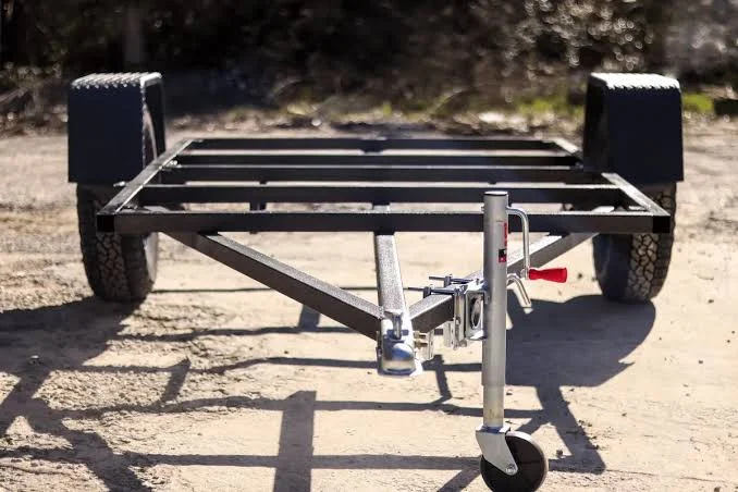
In commercial semi-trailer and heavy-duty chassis manufacturing, the structural skeleton—including side underrun protection guards (SUPDs), stanchion uprights, roof bows, and cross-members—demands high-strength, torsional rigidity. These assemblies rely predominantly on heavy-gauge square, rectangular, and round steel tubing, frequently ranging from 40×40mm up to 150×150mm with wall thicknesses between 2.5mm and 6.0mm.
Historically, trailer fabrication shops processed these structural profiles through a disconnected series of manual operations: band saws for rough-cutting, manual layout marking, plasma torches for fish-mouth saddle profiling, and intensive angle-grinder deburring. This workflow is not only labor-intensive but also creates severe dimensional bottlenecks. Today, deploying an industrial máquina de corte por láser de tubos transforms this fragmented fabrication line into a synchronized, single-step production cell.
Beyond raw cutting speed, selecting a máquina de corte por láser de tubos for structural trailer production requires balancing kinematic clamping stability, remnant waste reduction, 3D weld preparation, and automated material handling. This operational guide examines the four foundational engineering and economic rules that govern heavy trailer tube processing.
Ⅰ. Four-Chuck Avoidance Architecture: Achieving ≤40mm Remnants on Heavy Profiles
1. The kinematic bottleneck of conventional dual-chuck cutting
Traditional tube lasers rely on a two-chuck architecture: a fixed front chuck that guides the material and a traveling rear chuck that feeds the tube forward along the X-axis. This mechanical setup imposes a severe operational penalty: the cutting head cannot physically traverse past the front chuck jaws without risking a catastrophic mechanical collision. Consequently, the final section of every incoming 6-meter or 12-meter structural tube—typically measuring between 150mm and 250mm—remains unsupported in the cutting zone and must be discarded as scrap.
For a trailer builder processing 1,000 tons of high-strength rectangular tubing annually, a recurring 200mm remnant per 6-meter stick equates to roughly 3.3% raw material loss. Under current steel pricing, throwing away 33 tons of structural tubing per year directly erodes the gross margin of each trailer chassis.
2. Four-chuck synchronized motion and zero-scrap mechanics
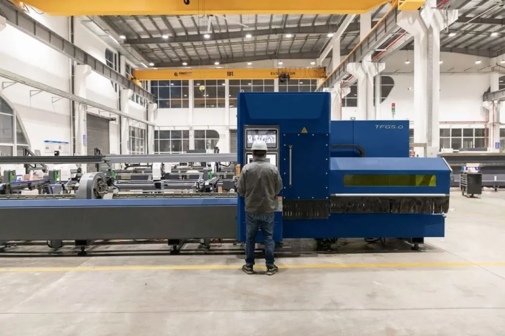
To eliminate this structural waste, a heavy-duty máquina de corte por láser de tubos utilizes a four-chuck synchronized kinematic system (two feeding chucks and two receiving chucks). As the raw profile advances, the four independent pneumatic chucks operate in a continuous “push-pull-avoid” handoff sequence:
- Pre-clamping and through-feed: The two rear chucks feed the raw tube while the middle chuck clamps and stabilizes the profile near the cutting nozzle.
- Synchronized handoff: As the cut approaches the tail end of the tube, the middle and front chucks clamp the work-piece while the rear chuck opens, advances, or shifts laterally to clear the cutting head envelope.
- Internal jaw penetrating cut: The cutting head operates directly between the synchronized clamping chucks, cutting flush against the gripping face.
This multi-chuck coordinated motion reduces the final drop remnant to ≤40mm (effectively short-tailing or true zero-scrap). Furthermore, because long structural square tubes frequently suffer from longitudinal camber and raw mill twist, the four-chuck array provides continuous rigid clamping along the centerline, preventing tube deflection and whipping during high-speed rotation.
Table 1: Dual-Chuck vs. Four-Chuck Scrap and Clamping Comparison (6m Tube Baseline)
| Structural Parameter | Standard Dual-Chuck System | Four-Chuck Avoidance System | Operational & Structural Advantage |
| Typical Remnant Length | 150 mm – 250 mm | ≤ 40 mm (Zero-waste optional) | Recovers up to 210mm of usable tube per cycle |
| Material Scrap Rate | 3.33% (avg. 200mm) | 0.67% (max 40mm) | 80% reduction in raw steel waste |
| Annual Scrap Loss (1,000t) | 33.3 Tons | 6.7 Tons | 26.6 Tons of high-strength steel saved |
| Tube Clamping Mechanism | Single-point push + guide | Four-point dynamic push-pull | Eliminates tube droop, sag, and rotational whip |
| Heavy Tube Support | External follower rollers | Synchronized chuck clamping | Maintains centerline accuracy on twisted tubes |

Ⅱ. 3D Saddle Cuts and Fish-Mouth Intersections: Eliminating Downstream Grinding
1. The challenge of non-planar weld preparation
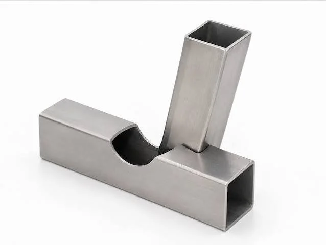
Trailer side guards, subframe outriggers, and ladder racks require round or rectangular tubes to intersect at complex acute angles (often 30° to 60°). Achieving a flush fit against curved or planar chassis rails requires compound saddle contours (fish-mouth copes) and precise weld bevels.
When performed manually, operators trace paper templates, cut the profile with handheld oxy-fuel or plasma torches, and spend minutes per joint grinding away dross to create a weld groove. Inconsistent manual fit-up leaves irregular joint gaps ranging from 2mm to 5mm. During downstream robotic or semi-automatic MAG/MIG welding, these gaps cause burn-through, require multi-pass weaving, and dramatically increase weld wire consumption.
2. 5-Axis 3D beveling directly from CAD
Equipping a máquina de corte por láser de tubos with a 3D bevel cutting head (A/B-axis tilt up to ±45°) transforms trailer frame pre-fabrication:
- Direct kinematic nesting: Structural CAD models (STEP/IGES) are processed directly into the machine CNC, automatically generating continuous fish-mouth paths and weld preps (V-groove, Y-groove, or K-groove).
- Interlocking mortise-and-tenon design: Instead of relying on manual jigs to position uprights on cross-members, the máquina de corte por láser de tubos cuts precision tabs and slots directly into the mating tubes. The components self-align and mechanically lock together before welding.
- Weld-ready cut faces: Nitrogen or high-pressure air assist gas ensures an oxide-free, dross-free edge conforming to ISO 9013 Range 2 standards, allowing robotic welding cells to operate without prior edge pre-cleaning.
Table 2: Joint Fabrication Cycle Time: Traditional Methods vs. 3D Tube Laser
| Fabrication Step | Manual Band Saw + Plasma + Grinder | 3D Tube Laser Cutting Machine | Process Impact |
| Marking & Layout | Manual template layout (2–4 min) | Automated CAD import (0 min) | Eliminates layout human error |
| Contour / Saddle Cut | Manual plasma torch (60–90 sec) | Fiber laser cutting (8–15 sec) | Precise, smooth kerf edge |
| Secondary Edge Grinding | Manual angle grinder (3–5 min) | None (0 min, 100% weld-ready) | Zero dross, zero burrs |
| Total Prep Time / Joint | 6 – 10 minutes | Under 20 seconds | >85% cycle time reduction |
| Downstream Weld Fit-Up | Irregular gap (1.5mm – 4.0mm) | Precision gap (< 0.2mm) | 40% reduction in weld consumable usage |
Ⅲ. Automated Bundle Loading: Maximizing OEE and Eliminating Crane Hazards
1. The material handling bottleneck in heavy tube fabrication
Structural steel tubes are heavy, awkward, and hazardous to transport manually across the shop floor. In traditional fabrication environments, loading a 6-meter bundle of 100×100×4mm square tubing requires an overhead bridge crane, rigging slings, and at least two workers to manually guide the bundle onto the machine bed.
This process introduces severe operational liabilities:
- Overhead crane dependency: The cutting machine frequently sits idle waiting for the shop crane to become available, dragging overall equipment effectiveness (OEE) below 45%.
- Workplace safety risks: Manual slinging and unbundling of heavy, oily steel tubes represents one of the highest injury risks in structural manufacturing (crushed fingers, foot trauma, and back injuries).
2. Automated bundle loading sequence and tube orientation
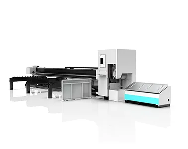
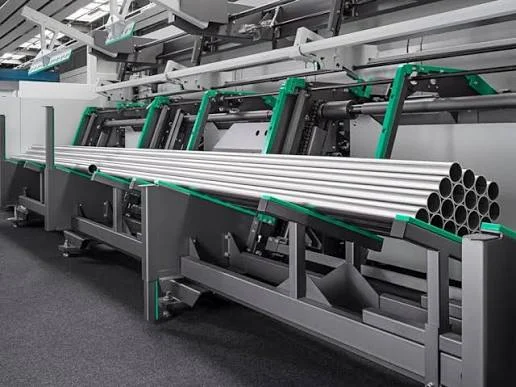
An automated bundle loader integrates seamlessly with a modern máquina de corte por láser de tubos, converting batch material handling into a continuous, untended feeding cycle:
- Bulk stage loading: A forklift deposits an entire 3-to-5-ton bundle of tubes into the heavy-duty storage magazine.
- Automated separation and singulation: Heavy lifting belts slowly unroll the bundle, separating the tubes into individual holding lanes without mechanical surface damage.
- Pneumatic clamping and seam detection: Optical and capacitive sensors detect the longitudinal weld seam of each square tube. The CNC automatically rotates the tube so the weld seam is positioned away from critical mounting hole locations and high-stress bend lines.
- Synchronized lateral infeed: The singulated tube is loaded onto the machine roller beds and clamped by the rear chucks in under 20 seconds, completely bypassing the shop overhead crane.
Table 3: Material Handling Metrics: Manual Crane vs. Automatic Bundle Loader
| Operational Parameter | Manual Overhead Crane Infeed | Integrated Automatic Bundle Loader | Operational Advantage |
| Loading Cycle per Tube | 60 – 120 seconds | 15 – 25 seconds | 4× to 5× faster infeed |
| Labor Requirement | 1 Machine Operator + 1 Crane Rigger | 1 Operator (supervising 2–3 cells) | Reallocates 1 dedicated worker |
| Crane Utilization | High crane demand (constant tie-up) | Zero crane requirement (Forklift only) | Frees crane for heavy final assembly |
| Machine Beam-on OEE | 40% – 55% | 80% – 88% | Doubled daily machine output |
| Weld Seam Alignment | Visual / Manual inspection | Automated vision/capacitive detection | Prevents holes on structural weld seams |
Ⅳ. The Capital Equipment Payback Ledger: A 3-Year Operational Cost Comparison
1. Evaluating CapEx vs. OpEx in structural trailer production
Evaluating a high-performance máquina de corte por láser de tubos requires analyzing total cost of ownership (TCO) rather than machine purchase price alone. While the initial capital expenditure for a four-chuck laser cell equipped with an automated bundle loader is substantially higher than conventional saws and plasma tables, the return on investment is driven across three quantifiable operating pillars:
- Scrap reduction: Compressing tube remnants from 200mm down to ≤40mm recovers tens of thousands of dollars in raw steel annually.
- Labor reallocation: Automating bundle loading and eliminating manual fish-mouth grinding reallocates 2 to 3 workers per shift to final chassis assembly.
- Downstream assembly velocity: Precision laser-cut interlocking tabs and zero-gap saddle joints allow welders and welding robots to assemble subframes twice as fast without rework.
2. Comprehensive 3-year financial model
The ledger below models an automotive trailer builder fabricating 600 flatbed/van trailers per year, consuming approximately 1,200 tons of structural rectangular tubing (Q235/Q355 or ASTM A500 Grade B).
Table 4: 3-Year Production Cost Ledger: Conventional Fabrication vs. Modern Tube Laser
| Operational Cost Category | Traditional Setup (Saws, Plasma & Grinding) | Modern Tube Laser Cutting Machine (4-Chuck + Bundle) | 3-Year Variance / Net Savings |
| Equipment CapEx / Financing | $0 (Fully amortized equipment) | $58,000 (3-year interest & tooling cost) | -$58,000 (Investment cost) |
| Material Scrap Cost (Tailing loss) | $95,800 (3.3% loss @ $1,050/t) | $19,300 (0.67% loss @ $1,050/t) | +$76,500 in steel saved |
| Direct Tube Cutting & Prep Labor | $216,000 (2 ops + 1 rigger, 2 shifts) | $72,000 (1 CNC operator) | +$144,000 in labor savings |
| Grinding Consumables & Plasma Tips | $42,000 (Discs, torches, nozzles) | $11,500 (Laser nozzles, protective lenses) | +$30,500 consumable savings |
| Downstream Welding Consumables | $64,000 (Excess wire for gap filling) | $38,000 (Tight fit-up robotic welding) | +$26,000 in wire & gas savings |
| Total 3-Year Operating Cost | $417,800 | $198,800 | $219,000 Net Operational Gain |
Under this heavy-gauge manufacturing volume, the capital equipment investment achieves full payback within 14 to 18 months, after which the structural steel recovery and labor efficiency directly contribute to operating profits.
Ⅴ. Frequently Asked Questions
How does a four-chuck tube laser cutting machine prevent tube whipping?
When long, heavy structural square tubes rotate at high RPM during cutting, any residual camber causes the ends to whip, deflecting the cut geometry. A four-chuck system maintains continuous pneumatic clamping on both sides of the cutting plane throughout the entire stroke. By dynamically clamping and supporting the tube along its center axis, it eliminates mechanical deflection, vibration, and angular taper.
Can a tube laser cutting machine process twisted or non-uniform mill tubes?
Yes. Commercial structural tubing from steel mills frequently exhibits dimensional tolerances, wall thickness variations, and slight twisting. Advanced fiber tube lasers utilize mechanical capacitive sensors and optical scanning systems to probe the four faces of the rectangular tube prior to cutting. The machine CNC automatically calculates the real-time twist angle and offsets the cutting path to maintain exact geometric accuracy.
What is the maximum wall thickness a tube laser can cut for trailer chassis?
Depending on the fiber laser power configuration, a modern machine equipped with a 6kW to 12kW resonator can easily process carbon steel tubing with wall thicknesses up to 16mm (0.63 in). For typical trailer side rails and stanchions with 3.0mm to 6.0mm walls, high-pressure compressed air or nitrogen assist gas enables clean, oxide-free cuts at speeds exceeding 6 meters per minute.
Referencias
- ISO 9013:2017 — Corte térmico — Clasificación de los cortes térmicos, International Organization for Standardization
- AWS D1.1/D1.1M — Structural Welding Code – Steel, American Welding Society
- ISO 8573-1:2010 — Compressed air — Contaminants and purity classes, International Organization for Standardization
- Artículo 179 del IRS: Opción de contabilizar como gasto determinados activos empresariales amortizables, Servicio de Impuestos Internos
Lecturas recomendadas
- Tube Laser Cutting Machine Price: Chuck Capacity & Payback — Comprehensive CapEx breakdown and chuck tonnage sizing.
- Tube Laser Zero-Tailing Chuck: Scrap Reduction & Payback Ledger — Detailed physics of pneumatic clamping and short-tail mechanics.
- Automatic Bundle Loader for Tube Lasers: Labor Savings & ROI — Automated tube handling and unbundling workflows.
- Large Format Laser Cutter: Trailer Chassis Fabrication & TCO Ledger— Heavy plate profiling and single-piece chassis rail fabrication.