

Investing in an industrial CNC laser cutting machine is not a simple machine tool purchase; it is a full-scale factory floor integration project. Plant managers and procurement officers frequently focus entirely on cutting speed specifications, sheet wattage, and CIF equipment prices, only to discover post-delivery that the factory entrance lacks clearance, the local power service cannot handle the concurrent electrical draw, or the shop floor lacks an efficient raw material flow.
Bringing modern metal laser cutting equipment online demands a comprehensive look at plant operations. This guide examines hardware configuration matching, operational machine envelopes derived from engineering drawings, dynamic floor load limits, and the electrical infrastructure required to ensure consistent uptime without unexpected civil engineering retrofit costs.
Ⅰ. CNC Laser Cutting Machine Hardware Configuration: Matching Components to Output
1. Control System Standardization and Human-Machine Interface
The computer numerical control (CNC) architecture dictates equipment productivity, programming overhead, and operator training speed. Across international sheet metal fabrication facilities, the Friendess CypCut (FSCUT) system represents the benchmark platform for standard and high-power metal fiber cutters.
From a shop-floor management standpoint, specifying an FSCUT control architecture reduces recruitment overhead because trained operators are widely available globally. Entry-level production cells running thin gauge parts typically utilize the FSCUT1000S or FSCUT2000C platform, featuring automatic nesting, dynamic lead-in assignment, and integrated capacitive height sensing. For thick plate and high-duty fabrication, advanced controllers like the FSCUT4000E and FSCUT6000 incorporate intelligent obstacle avoidance, dynamic edge-seeking, and automatic anti-collision routines that protect cutting heads from tilting cutouts.
2. Laser Source, Cutting Head Selection, and Consumables Pipeline
Procuring fiber laser cutting machine hardware requires evaluating long-term component availability, field service modularity, and consumable replenishment costs. Specifying globally supported fiber laser resonators—such as Raycus or Maxphotonics—ensures accessible warranty turnaround and straightforward field servicing without proprietary lock-in.
The optical train must pair with heavy-duty cutting heads (such as Raytools BM series or BOCI BLT series) equipped with sealed optical cavities and motorized autofocus mechanisms. While selecting cutting hardware, calculating the overall auxiliary system load is essential; implementing a dedicated high-pressure air compressor for laser cutting
allows fabricators to slash hourly assist gas expenses by 75% compared to delivered liquid nitrogen. Modular cutting heads with rapid-swap protective window drawers reduce maintenance downtime from hours to under five minutes.
Table 1: CNC Laser Cutting Machine Configuration Matrix by Fabrication Tier
| Machine Tier | Primary Target Applications | Typical Laser Power | Recommended CNC System | Resonator & Cutting Head | Shop Floor Operational Advantage |
| Light Gauge Job Shop | Enclosures, brackets, prototypes (≤6mm) | 1.5kW – 3kW | FSCUT1000S / 1500A | Raycus Single-Module / BOCI BLT310 | Low capital outlay, fast operator onboarding, minimal power requirements |
| Medium Fabrication | Mixed sheet metal, structural plates (≤16mm) | 6kW – 12kW | FSCUT2000C (CypNest) | Max Multi-Module / Raytools BM111 | High cutting velocity, worldwide parts supply, balanced utility draw |
| Heavy-Duty Production | Heavy machinery, thick carbon steel (≥20mm) | 12kW – 20kW+ | FSCUT4000E / FSCUT6000 | Raycus High-Power / BOCI BLT6X2 | Lightning fast piercing, active anti-collision, stable continuous duty |
Ⅱ. CNC Laser Cutter Footprint & Clearances: Static Dimensions vs. Real Envelope
1. The Discrepancy Between Shipping Size and Working Envelope
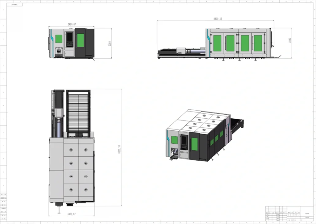
Equipment specification sheets generally state static chassis dimensions. A machine listed at 4,580 mm × 2,250 mm requires significantly more real estate once installed on the manufacturing floor. Machine footprint calculations must account for the rear-mounted dual-circuit industrial water chiller, the pulse-jet cartridge dust collector, the external electrical control enclosure, and the mandatory 1.2-meter perimeter buffer zone mandated for QBH optical fiber safety radius compliance.
+-----------------------------------------------------------------+
|                   1.2m Perimeter Service Clearance              |
|   +--------------------------+    +-------------------------+   |
|   | Water Chiller Unit &     |    | Main CNC Cutting Bed    |   |
|   | Exhaust Blower Ducting   |    | Enclosure & Motion Axis |   |
|   +--------------------------+    +-------------------------+   |
|   | 2.8m Console Swing Area  |    | External Shuttle Rails  |   |
|   +--------------------------+    +-------------------------+   |
+-----------------------------------------------------------------+
|               3.5m Heavy Material Logistics Aisle               |
+-----------------------------------------------------------------+
2. Single-Bed vs. Dual Pallet Exchange Clearances
A single-platform sheet metal cutter, such as the open-architecture YH3015F, occupies an operational envelope of 5,826 mm × 2,700 mm (15.73 m² total certified area) with an unladen weight of 1,318.11 kg. While compact, single-table systems require stopping the laser resonator during plate offloading and manual skeleton picking.
Installing a dual shuttle table drastically raises Overall Equipment Effectiveness (OEE). While one bed processes inside the enclosure, the external table is stripped and reloaded. However, integrating automated pallet shuttles directly impacts laser automation ROI
and spatial planning. A fully enclosed high-power system like the YH3015BD requires an operational footprint of 8,800 mm × 3,460 mm, consuming 30.45 m² of certified shop floor space. When evaluating oversized sheet stock, a 6-meter format gantry (such as the YH6025AG) demands a width exceeding 4,127 mm, requiring wide-span crane aisles.
Table 2: True Operating Footprint & Clearance Specifications
| Machine Architecture | Certified Model Code | External Dimensions (L × W × H mm) | True Operating Footprint (m²) | Operating Weight (kg) | Essential Shop Aisle & Clearance Directives |
| Open Single-Table | YH3015F | 4,580 × 2,250 × 1,700 | 15.73 m² | 1,318.11 kg | Compact cell footprint; requires 1.2m perimeter clearance for filter access. |
| Swing-Arm Single Bed | YH3015A / AJ | 4,550 × 2,280 × 1,850 | 12.74 m² | TBD (Configuration Dependent) | Requires 2.8m radial aisle space for ergonomic CNC console pivot. |
| Open Shuttle Table | 00.1530 Exchange | 8,216 × 2,205 × 1,965 | 18.12 m² | 2,972.97 kg | Shuttle infeed extends bed length to 8.2m; access needed for side scrap trays. |
| Enclosed Exchange Table | YH3015BD | 6,575 (+5,271) × 2,277 × 2,308 | 30.45 m² | 4,391.01 kg | Total working cell reaches 8.80m × 3.46m; requires overhead hook clearance. |
| Combo Sheet & Tube | YH3015FB | 8,385 × 4,616 × 2,231 | 38.70 m² | 3,448.40 kg | Lateral rotary chuck structure expands floor width to 4.6m. |
| Large Format Platform | YH6025AG | 7,880 × 4,128 × 2,120 | 32.53 m² | 5,500 kg (Approx.) | Oversized transverse width; necessitates heavy-capacity bridge crane handling. |
Ⅲ. Civil Engineering: Foundation Load & Vibration Isolation
1. Concrete Slab Depth and Dynamic Gantry Forces
Fiber laser cutting machines are dynamic machine tools. Modern lightweight extruded aluminum crossbeams operate with acceleration profiles between 1.2G and 2.5G. Rapid axis direction changes transfer high dynamic forces into the concrete subfloor through localized leveling footings.
For entry-level machines below 2.0 metric tons, a flat, cured industrial slab of 150 mm (6 inches) with standard welded wire mesh and C25 compressive strength is acceptable. However, industrial high-power exchange machines (3.0 to 5.5 metric tons bare weight) necessitate a minimum 200 mm to 250 mm (8 to 10 inches) reinforced concrete pad. The slab must incorporate a double-grid #4 structural rebar arrangement (200 mm spacing) to prevent differential foundation deflection that causes gantry guide rail binding.
       WORKSHOP SLAB & VIBRATION TRENCH PROFILE
+-----------------------------------------------------------------+
| Main Workshop Slab (150mm C25 Concrete)                         |
+-------------+  +---------------------------------+  +-----------+
              |  | 50mm Foam Isolation Joint       |  |
              |  +---------------------------------+  |
              |  | Dedicated Laser Foundation Pad  |  |
              |  | (200mm - 250mm Depth, C30 Mix)  |  |
              |  | Double-Grid Rebar Reinforcement |  |
              |  +---------------------------------+  |
              |  | Compacted Crushed Stone Sub-Base|  |
==============+==+=================================+==+============
2. Environmental Shock Isolation and Edge Striation Control
Optical laser processing requires isolation from exterior dynamic shock. Operating mechanical stamping presses, plate shears, or forge hammers within a 25-meter radius sends harmonic shock waves through connected ground concrete. These ground oscillations manifest as kerf rippling, micro-chatter marks, and tapered cut edges violating ISO 9013 Class 2 tolerances.
When ambient floor vibration exceeds 0.05G, civil work must include an isolated inertia pad. Contractors saw-cut a 50 mm continuous trench enclosing the entire machine footprint, filling the gap with closed-cell polyurethane isolation board or asphalt expansion filler. This physical air gap dampens harmonic energy, keeping precision linear guideways undisturbed.
Table 3: Equipment Weight Classes vs. Foundation Civil Engineering Standards
| Equipment Weight Class | Representative Machine Setups | Minimum Cured Slab Depth | Concrete Mix & Rebar Structure | Allowable Leveling Tolerance | Anti-Vibration Engineering Measures |
| Light Class (<2,000 kg) | 3015 Single Table (YH3015F) | 150 mm (6 in) | C25 Mix; single-layer 6-gauge wire fabric | ≤3.0 mm across 2,000 mm span | Standard shop perimeter expansion joint. |
| Medium Class (2,000–5,000 kg) | Enclosed Shuttles (YH3015BD) | 200 mm – 250 mm (8–10 in) | C30 Mix; dual-grid #4 (12mm) rebar @ 200mm | ≤2.0 mm across 3,000 mm span | Continuous perimeter isolation joint if near press lines. |
| Heavy Class (>5,000 kg) | 6025 Gantries, Combo Beds | 250 mm – 300 mm (10–12 in) | C35 Mix; dual-grid #5 (16mm) rebar @ 150mm | ≤1.5 mm across full rail length | Dedicated inertia pad with structural anchor tie-downs. |
| Continuous Coil Lines | 20m Blanking Systems (YH4515KA) | 350 mm – 450 mm (14–18 in) | Reinforced civil foundation pit with deep footings | ≤1.0 mm along leveler points | Full civil concrete pit isolated from shop floor. |
Ⅳ. Power Infrastructure & Auxiliary Utilities for Metal Laser Cutting Systems

1. Cumulative Electrical Load Sizing (kVA Multiplier)
A common mistake in equipment procurement is sizing facility electrical drops solely to the laser source’s nominal wattage. A 12kW optical oscillator converts wall-plug electricity at roughly 35% efficiency, pulling approximately 34 kW of raw electric power.
Operating cells require sizing service capacity for the total simultaneous load: the laser generator, dual refrigeration water chiller, pulse-jet exhaust fan, AC servo axes, and continuous high-pressure air compressors. When planning facility drops, plant engineers use this calculation:
$$\text{Minimum Transformer Capacity (kVA)} = \frac{\text{Total Connected System Power (kW)}}{0.85 \text{ (Power Factor)}} \times 1.25$$
For a standard 12kW fabrication cell pulling 78 kW of continuous peripheral power, the main distribution sub-panel requires a dedicated 115 kVA drop protected by an industrial automatic voltage stabilizer (±2% regulation).
                      ELECTRICAL SERVICE DISTRIBUTION
   480V / 3-Phase Main Shop Drop
                │
   [Voltage Stabilizer Unit (±2%)]
                ├────────────────────────────┐
                ▼                            ▼
   [CNC & Resonator Core]        [Auxiliary Sub-Panel]
   • Dedicated Grounding Rod     • Dual-Circuit Water Chiller
     (<1.5 Ohm Earth Ground)     • Pulse-Jet Dust Collector
                                 • 16-Bar Assist Air Compressor
2. Global Voltage Compliance and Independent Earth Grounding
Industrial machines ship pre-configured for standard three-phase industrial grids: 480V/60Hz across North America, or 380V–415V/50Hz throughout Europe and Asia. When connecting overseas machinery to domestic service, installing an industrial isolation transformer eliminates harmonic cross-talk between high-frequency laser power supplies and local shop distribution circuits.
Additionally, a fiber laser requires an independent, solid copper earth grounding rod driven adjacent to the machine foundation, achieving a certified resistance of less than 1.5 Ohms. Tying laser ground lines to shared factory structural steel causes transient voltage surges that damage digital servo encoders and internal diode modules.
Table 4: Electrical Supply, Chiller Load & Assist Gas Requirements Across Power Tiers
| Laser Output Tier | Total System Power Draw | Recommended Transformer | Minimum Chiller BTU/hr | Copper Cable Section (400V 3-Ph) | Dedicated Assist Gas Piping Standards |
| 3kW Fiber | 24 kW – 28 kW | 40 kVA | 40,000 BTU/hr | 16 mm² (AWG 5) | DN15 (1/2″) Stainless Tubing, 20 Bar rated |
| 6kW Fiber | 44 kW – 50 kW | 75 kVA | 85,000 BTU/hr | 35 mm² (AWG 2) | DN20 (3/4″) Stainless Tubing, 25 Bar rated |
| 12kW Fiber | 76 kW – 86 kW | 120 kVA | 160,000 BTU/hr | 70 mm² (AWG 2/0) | DN25 (1″) Stainless Pipe, 30 Bar rated |
| 20kW Fiber | 118 kW – 135 kW | 180 kVA | 260,000 BTU/hr | 120 mm² (AWG 4/0) | DN25 (1″) Stainless Pipe, 35 Bar rated |
Ⅴ. Lean Workshop Logistics, Crane Handling & Material Flow
1. U-Cell Layout vs. Linear Material Paths
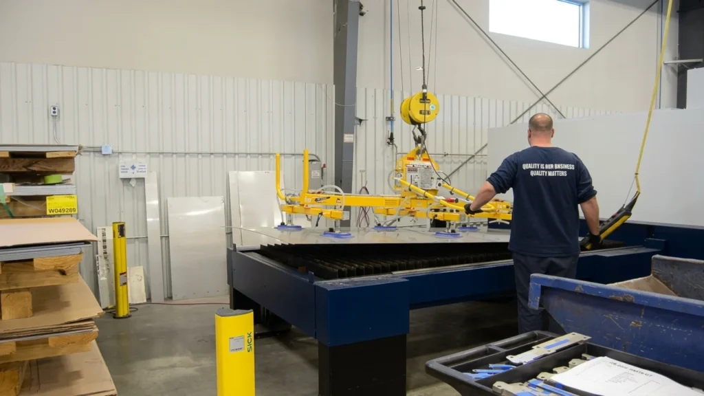
A laser cutting system generates revenue only when the beam is actively melting metal. When material handling relies on improvised forklift trips, laser beam-on efficiency (arc-on time) drops below 50%.
Implementing a U-shaped manufacturing cell isolates raw material delivery from sorted finished parts. Raw plate bundles sit directly within the primary overhead crane bay. Plates move through the loading station onto the shuttle table, while finished nests cycle outward onto an unloading sorting station. Processed parts route directly toward downstream press brakes, while scrap skeletons drop straight into rolling hoppers without crossing the raw sheet supply lane.
                         LEAN CELL MATERIAL CYCLE
   [Raw Material Rack] ──(Overhead Vacuum Hoist)──► [Laser Infeed Shuttle]
            ▲                                                 │
            │                                           (Pallet Swap)
   [Forklift Drop Zone]                                       ▼
            ▲                                       [Laser Outfeed Shuttle]
            │                                                 │
   [Scrap Skeleton Bin] ◄──(Skeleton Removal)───── [Manual / Robot Sorting]
                                                              │
                                                  (Sorted Blanks to Bending)
2. Overhead Crane Clearance and Vacuum Lifter Hooks
- Ceiling Hook Clearance: Safely operating a sheet-handling vacuum lifter requires a minimum clear crane hook height of 4.0 to 4.5 meters (13 to 15 feet) from the floor to the lowest structural rafter. This space accommodates bridge runway beams, hoist wire drums, vacuum suction spreader frames, and clear swinging room over enclosure light curtains.
- Aisle Width Clearances: Main factory transit corridors handling standard 1,500 mm × 3,000 mm steel stock require a clear width of at least 3.5 meters (11.5 feet) to accommodate 3-ton counterbalance forklifts carrying side-loaded plate packs. Handling 2,000 mm × 4,000 mm or 6,000 mm long stock requires expanding corridors to 4.5 meters.
Ⅵ. Pre-Installation Site Readiness Checklist
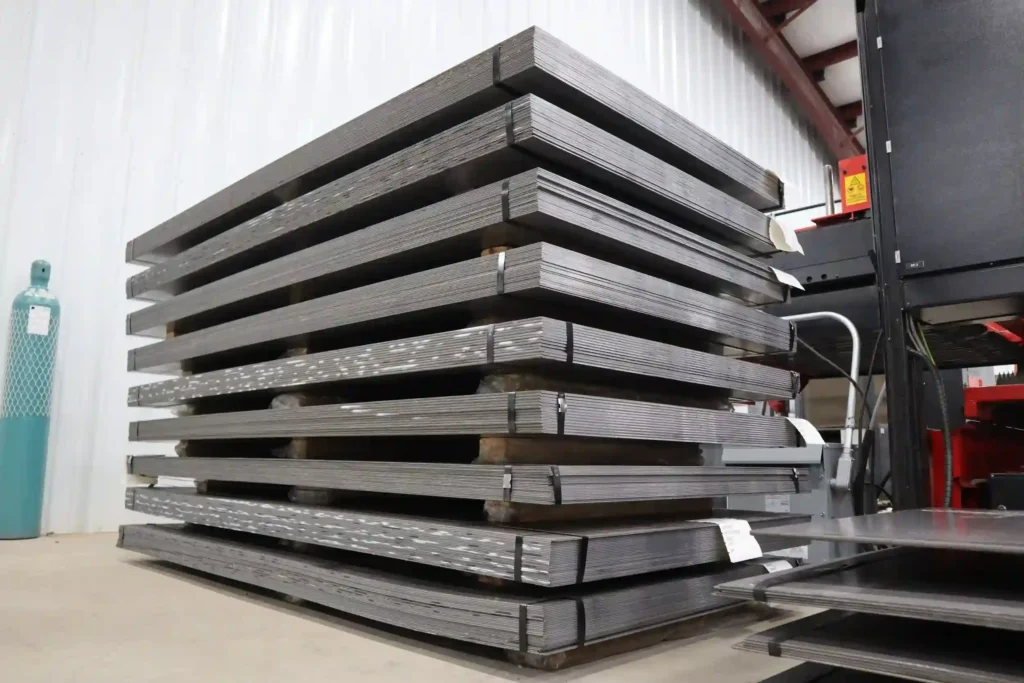
Plant operations teams should complete this physical readiness audit prior to authorizing equipment offloading and uncrating:
  ================ PRE-INSTALLATION SITE AUDIT ================
  [ ] 1. BUILDING CLEARANCE & RIGGING ENVELOPE
      ├── Overhead rolling door width exceeds crated width by ≥500mm.
      └── Rigging pathway verified for underground utility cover ratings.

  [ ] 2. FOUNDATION INTEGRITY & DAMPENING
      ├── Concrete core test confirms ≥200mm depth of C25/C30 grade.
      └── Floor slab leveled to within 2.0mm across 3.0m span.

  [ ] 3. ELECTRICAL SUPPLY & ISOLATED GROUNDING
      ├── Voltage stabilizer installed; phase variance holds within ±2%.
      └── Independent copper earth rod tests to under 1.5 Ohms resistance.

  [ ] 4. PNEUMATIC PIPING & DRY AIR PURITY
      ├── Assist gas piping pressure tested with zero drop over 24 hours.
      └── Air compressor filtration verified compliant with ISO 8573-1.

  [ ] 5. INDUSTRIAL FUME DUCTING & VENTILATION
      ├── Pulse-jet collector ducting routed with minimal 90-degree elbows.
      └── Spark arrestor traps positioned prior to main filter elements.
  ==============================================================
Treating facility preparation with the same engineering rigor as machine selection ensures high-power CNC laser cutting equipment arrives to a seamless installation, protecting capital investments and accelerating time-to-first-part production.
Frequently Asked Questions
What floor space is required for a CNC fiber laser cutter?
A single-table 3015 machine occupies roughly 15.7 m², while an enclosed dual pallet shuttle requires at least 30.5 m². Facilities must also add a 1.2-meter perimeter service buffer, raw sheet storage space, and 3.5-meter forklift aisles.
What concrete foundation thickness is required for an industrial laser cutter?
Standard single-table models (1.3 tons) require a 150 mm cured concrete slab. Dual exchange table systems (4 to 5 tons) require a 200 mm to 250 mm reinforced slab with double-grid rebar to support dynamic gantry acceleration forces.
No. High-power fiber laser resonators and digital servo drives are sensitive to voltage fluctuations. Welding equipment creates transient voltage spikes. A laser cutting machine requires an isolated breaker drop, an automatic voltage stabilizer, and a dedicated ground rod with <1.5 Ohms resistance.
How much overhead crane clearance is required for loading steel plates?
A minimum vertical clearance of 4.0 to 4.5 meters (13 to 15 feet) between the floor and the lowest crane hook is recommended. This height accommodates the hoist trolley, motorized vacuum sheet spreaders, and clearance over the laser machine enclosure.
Why is CypCut FSCUT the standard control system on metal laser cutters?
CypCut (FSCUT) is widely standardized due to its ease of programming, integrated CAD/DXF nesting capabilities, and intuitive edge-finding features. Its global adoption makes recruiting and training qualified laser operators faster and less costly.
Tài liệu tham khảo
- ISO 9013:2017 Thermal Cutting Tolerances — Thermal cutting: Classification of thermal cuts, geometric product specification and quality tolerances. International Organization for Standardization.
- NFPA 79 Electrical Standard for Industrial Machinery — Standard on electrical and electronic equipment of industrial machines to safeguard operators and equipment. National Fire Protection Association.
- ISO 8573-1:2010 Compressed Air Contaminants & Purity Classes — Purity classes of compressed air with respect to particles, water, and oil. International Organization for Standardization.
Tài liệu tham khảo thêm
- Laser Automation ROI: Pallet Changers & Loading Systems: Calculate how dual shuttle beds and material handling towers multiply cutting hours and reduce manual rigging[cite: 10].
- Air Compressor for Laser Cutting: Cut Gas Costs by 75%: Complete guide to pressure dew points, rotary screw packages, and air filtration standards[cite: 10].
- 12kW Fiber Laser Cutting Machine Price & Upgrade Guide: Economic breakdown of stepping up to high-wattage cutting and evaluating transformer upgrades[cite: 10].
- Chi phí máy cắt laser tính theo giờ: Sổ cái vận hành đầy đủ: Calculate consumables, electricity, maintenance, and operator labor into an accurate hourly rate[cite: 10].